
- 01 Piezoresistive Cantilever Testing
- 02 Electroactive Polymer Testing

Piezoresistive Cantilever Testing
A common sensing principle of MEMS-based sensors involves the inclusion of a piezoresistive element into the sensing structure. As the sensing element is strained, the electrical resistance of the piezoresistive element changes.
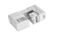
To increase the efficiency of dip-pen nanolithography systems, the MEMS chip shown here features an array of six cantilevers for parallel writing. To correct for the tilt angle between the cantilever array and the sample substrate, each cantilever is equipped with a piezoresistive sensor that measures the contact force of each cantilever. The piezoresistive elements have been fabricated through ion implantation, and a Wheatstone bridge has been integrated into the system to accurately convert the small resistance change into a voltage change.
In this application example, the stiffness of each cantilever is investigated in an automated manner. Consistent stiffness within the array is important property that determines the performance of the MEMS chip.
Electroactive Polymer Actuator Testing
Conjugated or conducting polymers are receiving significant attention as smart materials for novel microfabricated devices, such as actuators and sensors. In this application, the deflection range, actuation force, and time response of the beam-shaped electroactive polymer (EAP) actuator are tested.
Beam-shaped microactuators are clamped between two electrodes, enabling the application of the actuation signal to drive the microactuator. The top graph illustrates the maximum deflection of the EAP actuator beam versus the actuation voltage. The lower graph shows the driving force generated by the EAP actuator, as well as the square-wave driving signal plotted versus time.
More Applications

Soft Materials Testing
READ MORE ->
Read More
Nanoindentation
READ MORE ->
Read More
Mechanical Microscopy
READ MORE ->
Read More
Correlative Mechanical Microscopy
READ MORE ->
Read More
Scratch Testing
READ MORE ->
Read More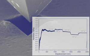
Strain-Rate Control
READ MORE ->
Read More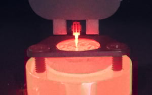
High-Temperature Testing
READ MORE ->
Read More